TVR T350
TVR T350

MENU

1700 XFLOW
ESCORT
1700 XFLOW
ESCORT
This vehicle is a 1978 MK2 Escort which we all know and love. The body shell is in good condition and the owner has done a few sporty upgrades to enhance the vehicles appearance and handling. I did some work on the engine some 12 months ago, mainly to the cylinder head to correct a misfire and make the engine perform as well as possible. However, it had done many thousands of miles and was very tired and worn out. We discussed the possibility of improving the power output of the engine but after the unit started making some rather worrying knocking noises, it was decided to carry out a full rebuild.
The capacity was to be increased to 1700cc with new forged pistons and the flywheel replaced with a lightweight steel item. The whole crankshaft assembly is to be dynamically balanced with an up rated clutch, and a camshaft that will maximise the performance but still retain lots of low down torque. The cylinder head will have the largest valves that can be fitted to a X Flow and fully ported to a Stage 5 spec. It will be fed with two 40 DCOE Weber carburettors and a hi spec tubular exhaust system. The end result should realise around 165bhp which in a little Escort should be a very exciting drive. The pictures below tell the story from a tired old lump to a gleaming performance engine with all the usual custom trimmings.
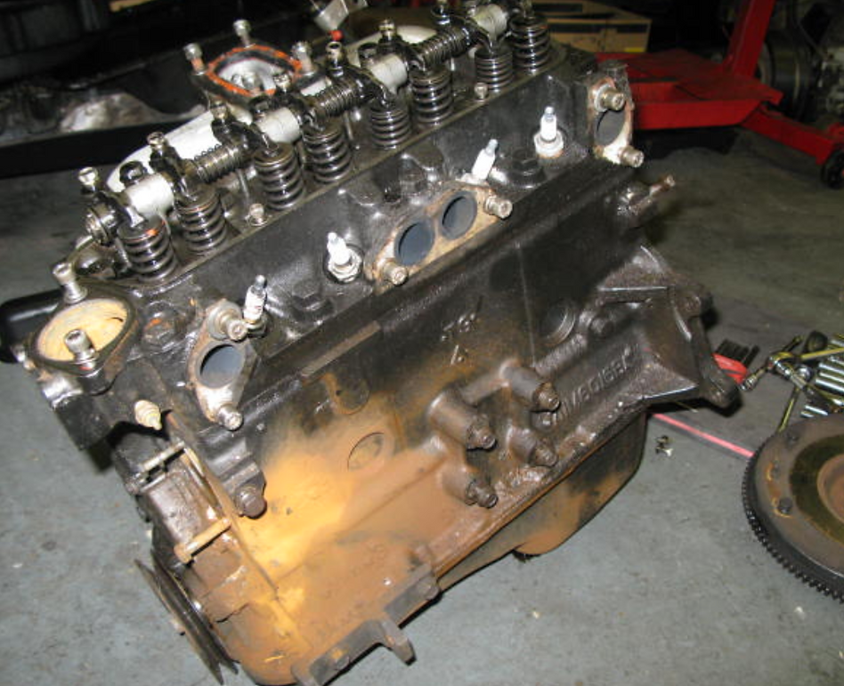
Well here is a very tired and worn out old X Flow engine. It had a leaking water pump, a completely smashed cam follower and both the front two pistons had shattered piston rings. The engine was carefully taken apart and thoroughly cleaned before being sent away for reboring, re-grinding and balancing. The cylinder head was obtained from another engine and had been partially modified, but not to the extent that would be required for this project.

The picture on the left shows the installation of new core plugs which have had a special sealant applied before fitting. The picture on the right is of the old paint being removed with a paint stripper prior to being re-finished in black.
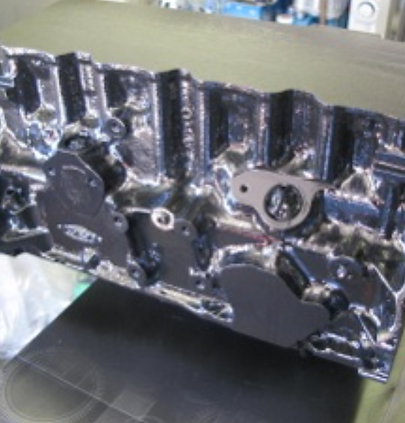

On the left is the block freshly painted in POR15 engine lacquer, looking very smart. The other shot shows the block set up on the engine stand ready to start building. The block is fully de-greased and spotlessly clean, the first job is the installation of the crankshaft and flywheel.


Above is the modified breather outlet and the fuel pump blanking plate. The mechanical pump wouldn’t be up to the job on the new engine, so a high output electric one will replace it. The breather will route via the rocker box and then on to a special catch tank. On the right is the crankshaft and camshaft installed along with a set of new performance followers.
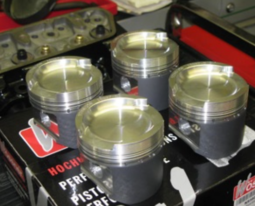

Above are the new forged pistons and on the right the components for the piston assembly. Note the conrod bolts on the left are ARP Hi-Tensile items which allow the engine to safely rev to 8000rpm. The conrods have been matched so they are all the same weight.

The piston with the conrod and piston rings fitted, ready to be installed in the block. On the right a piston ring has been fitted in the newly bored cylinders. A feeler gauge is slid in the gap where the ends of the ring meet to check the clearance. On this particular ring, the gap should be 12 thou. This is to allow for expansion of the ring when the engine is running, too tight a seizure can be an issue, too loose and a perfect seal may not be achieved.


The piston ring compressor fitted to a piston being installed in the bore. On the right, all four pistons fitted and lubricated with a special PTFE oil to help with the initial start up.


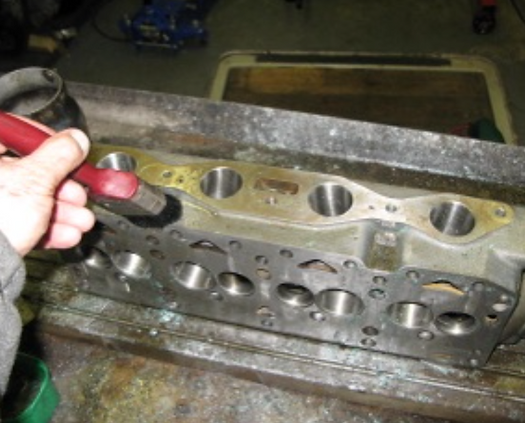
The cylinder head prepared for assembly. The springs needed shims underneath the base plates to achieve the correct spring hight and tension. The valve seals are modified ones as the head is now running twin springs and if the original seals are used, they will foul the inner spring. On the right and below shows the completed head. The valves are as big as you can fit in the head without them touching or the area between them in the head cracking. Should make for an awesome engine as the head is as modified as you can make it, just look at those valves, amazing.


The new ARP Hi-Tensile cylinder head and flywheel bolts ready for fitting to the engine. On the right, the studs fitted to the block and the competition head gasket installed ready for the head.

The cylinder head fitted to the block and torqued down with the uprated head studs. This upgrade should prevent any unwanted head gasket failure when the engine is working hard.
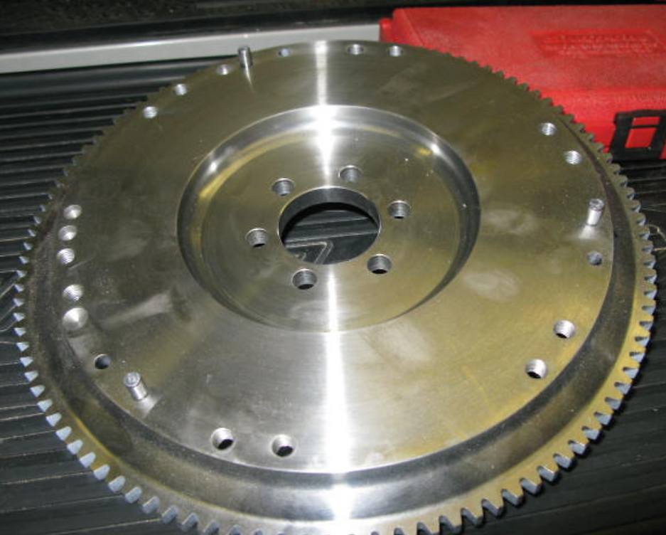
This is a lightweight billet steel flywheel from TTV Racing which is beautifully made and about half the weight of the original cast iron one. It will be held on to the crankshaft with ARP Hi Tensile bolts to complete the job. The friction and pressure plate are also uprated to cope with the extra power this unit will produce.

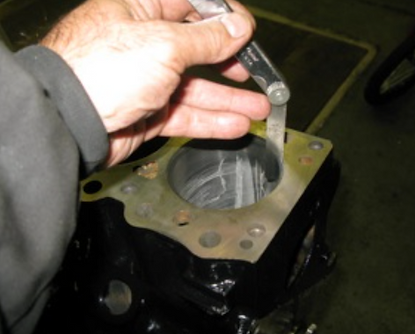
The rocker shaft that was supplied with this engine had holes in the steel pedestal that were 10.2mm diameter whereas the threads in the head are 3/8”UNC (8.5mm) which meant that the whole assembly “rattled” around the bolts. Also the centres of the shaft didn’t align with the centres on the cylinder head. So, I made some 10mm studs with 3/8” UNC threads cut at one end. Here you can see the studs I made installed in the head. The next task is to modify the rocker shaft pedestals to make the centres align.

The engine finished as much as possible, certainly very different from the unit I started with. Just hope it all fits with those carburettors bolted on.
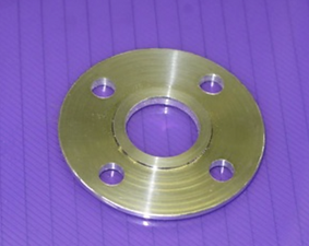
The original water pump had a viscous fan fitted to it which spun all the time cooling the radiator. While this is acceptable on a normal engine, it saps precious horse power and so is to be replaced with an electric unit. The new pump shaft is smaller than the old one so I had to make a locating disc so that the pump and pulley run concentrically. The bottom shot shows the pulley fitted to the pump along with a refurbished alternator.


These three pictures show the engine being timed up. The camshaft is set at 103 degrees ATDC at full lift on the No1 cylinder inlet valve. This process needs to be accurately carried out as if it is incorrect, the engine won’t run properly. The camshaft is fitted with an infinitely adjustable vernier sprocket to allow for precise adjustment.
Here the rocker pedestals are being machined to bring the centres in line by elongating the mounting holes on the outer two units. Hopefully it will all fit nicely and line up properly.


It was decided to repaint the engine bay satin black and to repair some rusty bits here and there. A new plate was welded into the RH flitch and all the suspension components were shot blasted and stove enamelled. The whole bay was painted in a protective POR15 primer and a coat of two pack satin black finish. Really transformed the look of the bay, it now has that finished performance appearance. The suspension was bolted back on with urethane bushes and new uprated coil over struts.
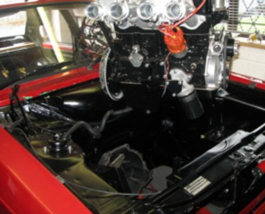

The engine being installed into the engine bay which after a bit of jiggling fitted a treat. Although what was once a roomy bay, has now been filled up with carbs and exhaust pipes not leaving as much room as I wanted for things like fuel filters, catch tanks etc. Some thought will be needed to get it all to fit neatly into place.
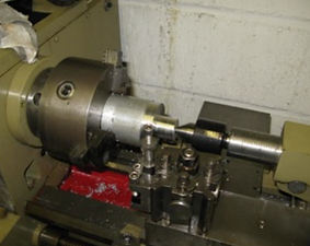
The left hand video, shows the bronze bar being machined to size. Here the part that will become the threaded section, is being turned to a diameter of 22mm, before being screw cut with the new thread.
On the right, the hexagonal part of the plug is being made, the part set up on the rotary table, which makes the process straightforward.
Once the hexagonal part is completed, the piece is put back in the lathe, for the thread to be screw cut. This is shown below, and the finished plug fitted to the block.