TVR T350
TVR T350

MENU


TVR TUSCAN
TVR
TUSCAN

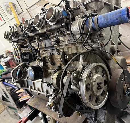
TVR designed their own engines in the late 90's, one was a 4.5 Litre V8 (AJP) and the other, a 4 Litre straight 6 (Speed 6). Whilst these engine have had their criticism over the years, they are, when properly maintained, powerful and reliable units. The Speed 6 has its foibles, like a lot of engines, but the design of the engine is very good. Like all things, it can be improved, and over the years these improvements have led to most of the issues being fixed.
The design of the valve train is perhaps the most criticised area, as it uses finger followers rather than a camshaft acting directly on to a bucket follower, like many production cars. However, if you look at some of the Formula 1 engines, this technology is still used today. It allows for a greater, and faster valve movement from the camshaft, which has a very positive effect on air flow and thus performance. TVR adopted this in their engine with good reason, but as the finger follower moves when the engine is running, it produces a side load on the top of the valve. This load can be reduced by using a roller follower, but TVR decided not to go this route probably due to cost. The net result over time, is the valve stems and guides wear, and oil starts to find its way into the exhaust, which can be seen as a smokey tailpipe. There are a few things that can be done to help prevent this, and these modifications will be shown in this engine build, along with a few other upgrades.
So, this project starts with removing the engine from the car. The engine will be completely rebuilt, replacing any components that are worn, or are to be upgraded. I won't show the engine being taken apart as that's not very interesting, but will show the engine being built, with various machining procedures that were necessary.
Once the engine and gearbox have been completed, the chassis will be removed form the body shell, for a full refurbishment.

The first problem, was metal evident in the oil, when it was drained from the main tank. There were metal particles around the drain plug, which weren't there before when the oil was changed only 1000 miles ago. On closer examination, the lobes on the exhaust camshaft were showing signs of wear, and the followers at the rear of the engine also had wear marks on them. This isn't unusual with these engines, as the oil feeding to the camshafts, and followers is only just enough, and the oil has a long way to go from the pump, to the exhaust valves and followers on No6 cylinder. When the engine is started, this area of the engine can suffer from lack of lubrication. The other problem was wear on the valve stems and valve guides. The video to the left shows the play in the valve. The valve stems were 5 thou down, and the guides nearly 10 thou. It doesn't sound much, but it meant that all the valves would need to be replaced, along with the guides. Interestingly the new guides are made of cast iron instead of bronze, and the valves are nitrided to make the metal on the valve more durable.
The next problem was the oil pressure relief valve plug. When I tried to undo the plug, it just went round, but wouldn't undo. After some persuading, I manage to get it out, only to find that it had been over tightened at some point, and all the threads in the block were badly damaged.
Lastly, the bolts that hold the auxiliary shaft bearing to the block, were heavily corroded and will need to be drilled out.
Taking the seized bolts first, the block was set up on the milling machine and the bolts carefully drilled out until the heads of the bolts could be removed. The bearing was then removed, leaving the threaded part of the bolt stuck in the block. These were drilled out, and with some heat, I managed to get the old bolts out. The block was then re-threaded to clean out the corrosion, and new bolts supplied.


The next task was to address the damaged threads in the block, where the oil pressure relief valve plug fits. As can be seen from the photo below, there was very little thread left, and not enough metal to re-thread it. So the block was set up on the mill, and the hole bored to a diameter of 20.50mm which is the tapping size for an M22x1.5 thread. Once the block had been threaded M22, an
oversized bronze plug would be made, similar to the original but with a larger thread diameter. Below, you can see the block being bored and the new thread being cut.


The picture on the right shows the finished thread in the block.
The next job, was to make a plug for the relief valve. It was important to make the new plug the same dimensions as the original, as the spring for the piston sits in a recess, which in turn, is at a set height to pre-load the spring. The following shots show the plug being made.


The water pump was the next item to address. In this engine, the water pump is located inside the engine, behind the front cover. In order to take the front cover off, the front crankshaft pulley and bolt needs to be removed. Unfortunately, this isn't possible with the engine in the car, so it is very important that a new pump. is installed prior to the engine being fitted for obvious reasons. Next problem! They don't make them anymore, but you can buy all the parts to rebuild the old one.
If you look at the old pump, it looks very beaten up, who knows what has happened. in the past, but it can be repaired.

Here you can see the pump casting stripped down and being machined to remove all the damage to the casting.
The kit comes with the new bearings, a new shaft and the seal that fits on the back of the pump. On the right, you can see the rebuilt pump, looking like a new one.
Below shows, the oil pump which has also been rebuilt with new bearings, and the scavenge pump which has had similar treatment.
There will be new timing chains fitted, and the "1/2 Time" sprocket will also have new bearings installed.

The last job to do on the block before assembly, is the white metal bearing that supports the auxiliary shaft. The old bearing was removed, and the block cleaned, making sure all the oil gallery's are clean and blown through. There is an oil feed to the auxiliary bearing, and it is important that the hole in the shell lines up with the oil feed in the block. Once the shell was installed, a new oil seal was fitted to the rear. The block was then meticulously cleaned, and is now ready for assembly.


Next, is the installation of the pistons. These have been cleaned up and measured. Remarkably, they are in very good condition, with little or no wear.
The big end bearings were also fitted and measured in a similar way to the main bearings with Plastigauge.
The new piston rings were fitted into the appropriate bore at a set depth, and the gaps on the ends of the rings measured with feeler gauges. The ring gaps were consistent throughout, and the wear on the bores is negligible. The piston rings were then fitted to each piston, lubricated and installed into each cylinder with a ring compressor. The big end bearings were lubricated with assembly lube, the caps fitted and torqued up. Once everything was assembled, the crankshaft was rotated to check all runs smoothly.


Not really a performance upgrade, but on the right, there is the old crankshaft washer. Seeing as the front cover has been vapour blasted, and the pulley painted gloss black, it was fitting to make a washer to enhance the look. The bolt will be chemically blacked to complete it. The top cam cover has also been vapour blasted, this will be ceramic coated which will stop the finish tarnishing. The coil pack cover is to be painted gloss black, the letters will be fly cut on the mill to reveal the letters in shinny metal. Again, ceramic will be applied to prevent corrosion.


Below is the block and the crankshaft, cleaned and ready for assembly. But first, the crankshaft is measured to check the journals are within limits. Then the main bearings are fitted to the block, and crankshaft carefully lowered into position. At this stage the bearings are dry, then a small piece of Plastigauge is placed on each journal, and the bearing caps fitted. The nuts are then torqued down, making sure the crankshaft isn't moved. Then all the nuts are undone and the bearing caps removed. The Plastigauge has now been squashed, and it is then compared to a scale which tells you the clearance between the journal and the bearing shell. All the bearings were between 1.5 thou and 1.7 thou which is ideal. The journals and bearings are cleaned and the crankshaft lifted out. Now the bearings are lubricated with engine assembly lube, and the crankshaft installed once again. The bearings in the caps are lubricated, and tightened to the correct torque. The crankshaft can now be rotated, checked for smoothness and any tight spots.

The sump casting was cleaned, and the baffle plate installed, along with the scavenge pump. The sump was then fitted to the block and a new rear crankshaft seal installed. The flywheel was then fitted to the crankshaft, but at this stage the clutch is left off, as a timing disc will need to be attached for the camshaft timing. On these engines, there are no timing marks, so the timing is done the old fashioned way, with clock gauges. I have made a complete set of tools and jigs for these engines, as there are many processes that require specialised tools.
The auxiliary shaft was then installed, along with a new belt for the power steering pump.


One of the problems with this engine as mentioned earlier, is that there is only just enough oil being fed to the valve gear. This wasn't in the original design, but ended up in the production engines. No6 cylinder exhaust valves suffer the most as the oil has a considerable distance to travel before reaching the followers. After a while, this can manifest itself with excessive wear on the camshaft lobe and follower. The modification you see in the next few photo's is a solution to the issue. Oil is routed to the rear of the engine and fed directly into the finger follower shaft. Now when the engine is first turned over, oil floods the valve train immediately. When the engine is back in the car, I'll include a video demonstrating this.
The top video shows the head set up on the mill, and an 8mm hole is being drilled through the casting where the rocker shaft sits. Then another hole 8.70mm is drilled 20mm into the head which is the tapping size for the banjo bolt. Finally the hole is threaded 1/8"BSP which then allows the pipe and fittings to be bolted to the head. The other end of the pipe, T's off the oil pressure pipe, which comes directly off the main oil gallery.
Another problem with these engines is the cylinder head bolts. They are a course thread being tightened into an alloy block. There have been many instances where head gasket issues have occurred, because of failed threads or incorrect torque on the bolts. With all competition engine I build, studs are used to alleviate this. Below are the new studs cut to size, ready to be screw cut. (left), and the finish product with M12x1.25 threads (right) These studs will have ARP nuts and washers fitted to them, and will be torqued to 80ft/lbs.


The video shown earlier, of the excessive wear in the valve guides was the next task to correct. There were a couple of problems here which were unexpected. The valve guides were worn in excess of 10 thou, and the valve stems 5 thou. Although this doesn't sound a lot, it meant that new guides would need to be installed, along with new valves. Where these valves were originally sourced from, I'm not sure, but instead of using a 7mm valve guide and valve, these are 6.95mm which is most unusual. The next problem was that the seals that fit on the valve guides were unavailable. So I chatted with a friend of mine at Vulcan Engineering, and he suggested using Cosworth seals as they are readily available. He also had a reamer, and seat cutter of the correct size for the guides, and kindly offered to machine the new guides (which were made of cast iron rather than bronze) to fit the Cosworth seals, and fit the guides. He then cut the seats for the new valves, which were nitrided, so hopefully this will improve the wear issues these heads suffer from. Below shows the freshly cut bronze seats, and on the right the head with the valves fitted.


The new cylinder head studs were fitted to the block, and the head installed. The picture on the right shows the new ARP washers and nuts fitted to the studs. There are new rocker shafts fitted, along with a new set of finger followers. It was also decided to install two new camshafts, as the original ones were worn. To be fair, it was the exhaust camshaft that was the badly worn one, but it now has two new ones. With the modified oil feed, the engine should enjoy many miles of trouble free motoring in the future. The next task is to re-shim the valves to obtain the correct clearances. As the seats have been re-cut, this will necessitate all the clearances to be reset. It's a time consuming task, but it needs to be accurately set up.


The cam cover and the coil pack cover plate have been vapour blasted to remove any corrosion. This leaves and semi shinny satin finish, which is reasonably corrosion resistant. The coil pack cover was painted gloss black, and then the painted surface machined to relieve the lettering. Then the painted plate and the vapoured surfaces were ceramic coated which will seal the metal and give a lasting protection against moisture. The finished parts can be seen below.

The exhaust manifolds were sent away to Zircotec, who shot blasted them, then applied a silver ceramic coating which is both attractive, and will help lower the engine bay temperature. This is a very high quality process, which although isn't cheap, is very durable and will last for years to come.
The left hand video, shows the bronze bar being machined to size. Here the part that will become the threaded section, is being turned to a diameter of 22mm, before being screw cut with the new thread.
On the right, the hexagonal part of the plug is being made, the part set up on the rotary table, which makes the process straightforward.
Once the hexagonal part is completed, the piece is put back in the lathe, for the thread to be screw cut. This is shown below, and the finished plug fitted to the block.